Two Terms Often Used Interchangeably — But They Are Not the Same
In the world of electronic interconnects, "wire harness" and "cable assembly" are frequently treated as synonyms in casual conversation, on datasheets, and even by experienced engineers. In a manufacturing context, however, they describe genuinely different constructs with different design requirements, manufacturing processes, and performance characteristics. Using the wrong term when speaking to a CM or writing a specification can result in a misquoted job or a product that does not meet your requirements.
This article defines each type clearly, explains the structural and functional differences, and gives practical guidance on when each is the right choice for your product.
Cable Assembly: Definition and Structure
A cable assembly is an organized grouping of one or more insulated conductors — individual wires or multi-conductor cables — that are terminated at both ends with connectors, contacts, or other termination hardware. The defining characteristic is that the conductors are enclosed within a common outer jacket or conduit that runs continuously from one terminated end to the other.
The outer jacket provides environmental protection (against moisture, abrasion, UV, chemicals), bundles the conductors into a manageable physical unit, and provides a predictable impedance environment for the electrical signals inside. Multi-conductor cables — such as a shielded twisted pair cable or a flat ribbon cable — are manufactured as a continuous raw material; the cable assembly manufacturer cuts to length, strips ends, and terminates with the specified connectors.
Common examples of cable assemblies include:
- USB, HDMI, and DisplayPort cables with molded connector boots.
- Coaxial cable assemblies with SMA, BNC, or N-type connectors.
- Multi-conductor shielded cables in medical equipment carrying sensor signals.
- Ethernet patch cables and trunk cables.
- Power cords with IEC connectors.
Cable assemblies are typically simpler in structure than harnesses and are more suited to point-to-point interconnections carrying a single signal type or a small number of related signals from one connector to another.
Wire Harness: Definition and Structure
A wire harness (also called a wiring harness or cable harness) is an organized assembly of multiple individual wires and cables that are routed together along a defined path and bound into a single unit using a protective covering — typically woven sleeves, braided shielding, corrugated conduit, PVC tape, lacing cord, or a combination of these materials. The harness then branches at defined points, with individual wires or sub-groups routing to different connectors or termination points.
The defining characteristic of a wire harness is the branching, multi-destination routing that serves as a complete wiring subsystem. A harness does not go from connector A to connector B — it goes from a main trunk to connectors A, B, C, D, and E, with specific wires breaking out at specific branch points.
Common examples of wire harnesses include:
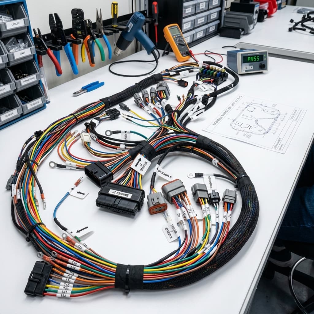
- Automotive engine wiring harnesses connecting the ECU to sensors, injectors, ignition coils, and ancillary modules throughout the engine bay.
- Aircraft avionics harnesses routing signals from avionics bays to cockpit instrumentation, actuators, and sensors throughout the airframe.
- Industrial machine harnesses connecting a control panel to motors, limit switches, solenoids, and HMI devices across a machine frame.
- Medical device internal harnesses connecting a main PCB to displays, sensors, motors, and external connector panels.
Structural Differences in Detail
Branching Topology
A cable assembly has a linear topology: one or more conductors running from point to point with a defined start and end. A harness has a branching topology: a main trunk from which sub-trunks and individual wires branch at defined breakout points, forming a tree-like structure. This branching is defined by a harness drawing that specifies every branch length, breakout location, wire gauge, color code, and terminal type.
Protective Covering
Cable assemblies rely on the cable's own jacket as the primary protective element. Wire harnesses, assembling individual wires that have no common jacket, require the protective covering to be applied during assembly. The choice of covering (expandable braid, corrugated split loom, PVC tape wrap, heat-shrink tubing at branch points) is driven by the environment: vibration, temperature, fluid exposure, and abrasion resistance requirements.
Manufacturing Process
Cable assemblies can be manufactured largely with automated equipment — wire cutters, strippers, crimping machines, and connector insertion tools. Wire harnesses require more manual labor, particularly at the branch points and at the routing steps where individual wires must be positioned on a formboard (a physical template that holds the harness in its correct routed geometry while it is taped or sleeved).
When You Need a Cable Assembly vs. a Wire Harness
Use a Cable Assembly When:
- You have a point-to-point connection carrying one signal type (power, data, RF, video) between two connectors.
- The connection path is simple — no branching required.
- The cable will be exposed to a defined environmental threat (moisture, abrasion) that is addressed by selecting the appropriate jacket material.
- The assembly will be ordered in moderate to high volume and benefits from automated termination processes.
- The cable is field-replaceable and needs to be handled as a discrete unit.
Use a Wire Harness When:
- Your product has multiple subsystems that need to be electrically interconnected along a defined physical routing path.
- Wires must branch to three or more destinations from a common trunk.
- Space is constrained and individual wires must be organized and bundled to fit within a defined envelope.
- The product operates in a harsh environment (automotive, aerospace, industrial) where organized, protected routing is required for reliability.
- The assembly is complex enough that having it pre-built and tested as a subassembly simplifies final system assembly.
Design Considerations
For cable assemblies, the key design decisions are conductor gauge (driven by current capacity and voltage drop), insulation material (temperature rating, chemical resistance, flexibility), shielding (for EMI-sensitive signals), and connector selection (mating cycles, current rating, environmental sealing). Specify these clearly in a cable assembly drawing with a wire schedule table.
For wire harnesses, a complete harness drawing package includes a wire schedule (every wire's gauge, color, start connector and pin, end connector and pin), a schematic showing the electrical connections, and a formboard or harness configuration drawing showing the physical routing, all branch lengths, and covering specifications. Incomplete harness documentation is the primary cause of errors and rework in harness manufacturing — invest the time to make it complete.
Testing Methods
Both cable assemblies and wire harnesses are tested against continuity, shorts, and Hi-Pot (high-potential dielectric) specifications before shipment.
Continuity testing verifies that each expected electrical path is present — that every wire connects the right source pin to the right destination pin.
Short circuit testing verifies that no unintended connections exist between conductors that should be isolated.
Hi-Pot testing applies a high voltage (well above operating voltage) between conductors or between conductors and shield/ground to verify insulation integrity. It is required for harnesses used in safety-critical, high-voltage, or regulated applications.
For high-reliability applications (aerospace, medical, automotive), cable and harness testing requirements are spelled out in standards such as IPC/WHMA-A-620 (Requirements and Acceptance for Cable and Wire Harness Assemblies) — the cable/harness equivalent of IPC-A-610. As with PCB assembly standards, specifying the applicable standard and class in your procurement documentation ensures your CM builds and inspects to a defined, verifiable bar.
EMS Technologies
Electronic Manufacturing Insights